Lab 1
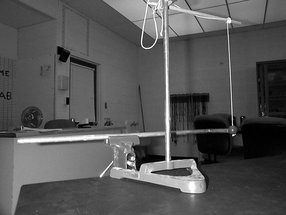
SHIVE WAVE MACHINE
EQUIPMENT: Shive Wave Machine with clamp; driver and metronome upon request.
PURPOSE: To demonstrate standing waves.
DESCRIPTION: Standing waves can be generated with either (1) both ends fixed, (2) one end fixed and one end free, or (3) both ends free. Either use your hand or the motorized drive; your hand possesses better feedback for small adjustments in frequency. A metronome is available for comparing the frequencies of various harmonics.
PURPOSE: To demonstrate reflection of pulses from fixed ends and free ends.
DESCRIPTION: A pulse generated at one end reflects off the opposite end. The reflecting end can either be free (left alone) or fixed (connected to a clamp).
PURPOSE: To demonstrate constructive and destructive interference using pulses.
DESCRIPTION: Starting identical pulses from both ends simultaneously, either in or out of phase, they can be observed as they pass. For two identical pulses, move your hand rapidly down and up at the center of the machine. The two pulses created will reflect off the ends and interfere as they cross each other on their return. Repeat this with one end clamped to get a phase reversal of the pulse which reflects off that end.
Lab 2
Longitudinal Waves in a Brass Rod
PURPOSE: To show wave energy transfer through an "L" shaped metal rod.
DESCRIPTION: The "L" shaped brass rod is clamped securely in a vise. A ball is suspended pendulum fashion so that it is in contact with the short segment of the rod. When the opposite end of the rod is struck sharply with a hammer, the wave energy travels through the rod and makes the ball swing.
EQUIPMENT: "L" shaped Rod, Vise, Hammer, Stand, and small pendulum.
Lab 3
BELL IN VACUUM
PURPOSE: To demonstrate that sound waves require a medium for propagation.
DESCRIPTION: Start the bell, then pump the air out of the jar. Air pressure in the jar is read by the large gauge. As the air is removed, the sound intensity decreases, ultimately to nearly zero. Turn off the vacuum pump when the jar is evacuated and crack the valve open, allowing air to re-enter the jar. As the pressure increases the sound of the bell comes back, but without the noise of the pump.
SUGGESTIONS: This is actually not as simple as it seems. Although the conclusion is correct, it is not strictly speaking demonstrated using this setup. Rather, this demonstrates an impedance mismatch between the very low pressure air in the jar and the glass, which cannot be moved sufficiently to transmit sound under these conditions. I would use it anyway and lie a little to perpetuate the myth.
EQUIPMENT: Jar with electric bell, vacuum pump and gauge, pre-assembled as photographed.
Lab 4
SPEAKER AND CANDLE
PURPOSE: To demonstrate that sound waves cause the air to vibrate longitudinally.
DESCRIPTION: A lighted candle is placed directly in front of the center of a large loudspeaker, which is operating in the 10 Hertz range. The motion of the candle flame is longitudinal, following the motion of the air, illustrating the longitudinal nature of sound waves.
EQUIPMENT: Loudspeaker, oscillator, and mounted candle.
Lab 5
BEATS AND RESONANCE - TUNING FORKS
PURPOSE: To demonstrate beats, and to demonstrate resonance between two nearly identical tuning fork resonators.
DESCRIPTION: Adding a small mass onto one of the tuning forks reduces its frequency. Striking two tuning forks, one with a weight, then produces beats.
EQUIPMENT: Two tuning forks one with extra mass, and striker.
Lab 6
DOPPLER EFFECT - TUNING FORK ON STRING
PURPOSE: To demonstrate the Doppler effect.
DESCRIPTION: A tuning fork is struck to activate the "clang tone" and whirled about the instructor's head on a string. The Doppler effect can easily be heard in a small classroom or a reasonably quiet lecture hall.
EQUIPMENT: Doppler tuning fork on string.
